

The instructions below are intended for setting the time on sewing machine models, it's a whole series of vintage Pfaff sewing machines, I have to list them all:
Pfaff 1222, Pfaff 1221, Pfaff 1214, Pfaff 1213, Pfaff 1212, Pfaff 1211, Pfaff 1199, Pfaff 1197, Pfaff 1196...
Likewise, this instruction can be applied to most sewing machines that have a rotating hook, everything is very similar, the specified special tools are not mandatory and especially necessary, the specified measures are also not "sacred letter" and you can slightly deviate from them.
Rule:
When the machine is set for straight stitching in the central needle position, and the
needle has risen 2 mm (5/64") from the bottom of its stroke, the point of the sewing
hook should be exactly opposite the center line of the needle at the back.
Check: (MasinskiKutak.com)
Turn the master selector dial to straight stitching and the needle position knob to the
central needle position. On machines fitted with automatic mechanism, erase all stitch
settings. In order to obtain a better view, remove the sewing foot and the needle plate.
Take out both screws of the bobbin case position finger bracket and dismantle the sewing hook. Insert a new System 130 needle in size 80 and bring the needle to the bottom of its stroke by turning the balance wheel (Fig. 36).
Attach the C clamp (No. 870-137-00) lightly to the needle bar.
Push the 2 mm gauge (No. 870-136-00) with its cutout onto the needle bar above the C clamp. Now push C clamp and gauge upwards against the needle bar frame as far as possible. Then tighten the screw of the C clamp
securely.
Turn the balance wheel back and forth slightly in order to check if the needle
bar is really at its lowest point. There must be no play between needle bar frame, gauge
and C clamp (Fig. 36).
Remove the gauge and rotate the balance wheel in sewing
direction until the C clamp is in contact with the needle bar frame (Fig. 36a).
The needle
bar has thus risen by 2 mm which is the amount of needle rise required to form the loop.
The hook point must now be exactly opposite the center line of the needle at the back. (MasinskiKutak.com)

Adjustment:
if the sewing hook is completely out of adjustment, remove the hook bearing cover and loosen both screws 2 of helical gear 3 (Fig. 36a). For this, loosen the C-clamp and repeat the adjustment described under "Check". Turn the sewing hook until its point is exactly opposite the center line of the needle at the back
(Figs.36 and 36a), With the sewing hook in this position, push helical gear 3 to the right and press it lightly against the bearing. Securely tighten screws 2.
Note:
If no screw is visible Fig. 36a when the helical gear is in the above position, pull helical gear 3 out and insert it again so that one of its screws accessible.
Verification:
Turn the balance wheel backward a little and then forward until the C clamp is again in contact with the needle bar frame. The point of the sewing hook must now be exactly opposite the center line of the needle at the back. Now remove the C clamp. Fully tighten both screws 2 of helical gear 3. Make sure that the hook drive shaft does not bind.
Setting the Needle Bar at the Correct Height:
The machine is equipped with a transverse, double-revolution rotary hook.
When the needle descends on the right of its throw in zigzag sewing, the hook point reaches the needle a little earlier: when it descends on the left of its throw, a little later. Consequently, the hook point is a little higher above the needle eye when the needle is on the right of its throw than when it descends on the left of its throw (Fig. 37). (MasinskiKutak.com)
Rule:
When the machine is set for its widest zigzag stitch and the needle descends on the
left of its throw, there should be a clearance of 0.5 mm (,02") between the top of the needle eye and the lower edge of the hook point (Figs. 37a and 37b).

Check:
Turn the master selector dial to stitch range 8 and the needle position knob to the central needle position. On machines fitted with automatic mechanism, erase all stitch settings. Remove the sewing foot and the needle plate. In order to obtain a better view, loosen both screws of the bobbin case position finger bracket and
dismantle the sewing hook.
Rotate the balance wheel in sewing direction until the needle descends on the left of its throw. Then continue turning the balance wheel until the needle rises again and the hook point is exactly opposite its center line at the back. The clearance between the top of the needle eye and the underside of the hook point should now be 0.5 mm (.02"), as illustrated in Figs. 37a and 37b).
Adjustment:
If this clearance in incorrect, remove the face cover and slightly loosen hexagon screw 11 (Fig. 37c), using a 5 mm spanner. Position needle bar 1 at the correct height, making sure that you do not turn it. Then lightly tighten hexagon screw 11 again.
Verification:
After sight-checking the needle bar height and the correct angle of the needle holder, tighten hexagon screw 11 securely.

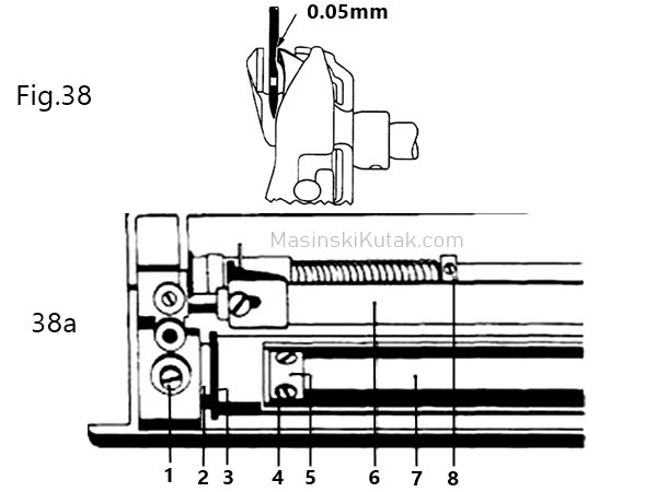
Setting the Hook to Needle Clearance:
With the machine set for straight stitching, the clearance between the hook point and the bottom of the clearance out of the needle should be 0,05 mm (.004"), as shown in Fig. 38. At the widest zigzag stitch setting, the hook point should almost touch the needle as it descends on the right and left of its throw.
Check:
Remove the sewing foot and the needle plate. Loosen both screws of the bobbin case position finger bracket and strip the sewing hook. Insert a new System 130 needle, No.80, and check the above clearance with the machine set for straight stitching and the widest zigzag stitch. (MasinskiKutak.com)
Adjustment:
If the clearance between sewing hook and needle has to be set a new, loosen hook bearing screw 1 (Fig. 38a). On free-arm machines, the base plate and the free arm bottom cover must be removed first. Position the sewing hook so that the above clearance is correct, taking care however that hook bearing 2 is not pushed to the
left and the feed rock shaft has no end play.
Then tighten hook bearing screw 1 securely, but make sure that the feed rock shaft does not bind.
Verification:
Make a sight check to ascertain if the clearance is correct in straight and zigzag stitching.
Adjusting the Bobbin Case Position Finger: (MasinskiKutak.com)
Rule;There should be a clearance of 0.7 mm (.03") between the position finger and the bottom of the slot in the bobbin case base.
Check:
The gauge should pass freely, but without play, between the position finger and the wall of the position slot in the bobbin case base (Fig. 39)
Final sentence: this instruction will seem too complicated for many, it's nothing unusual, if you want to learn something you have to be a little persistent, routine is acquired over time, it's like that in every job. Good luck ☺
No comments:
Post a Comment